Engine 2 - 600lbf Nitrous/IPA Liquid Rocket Engine
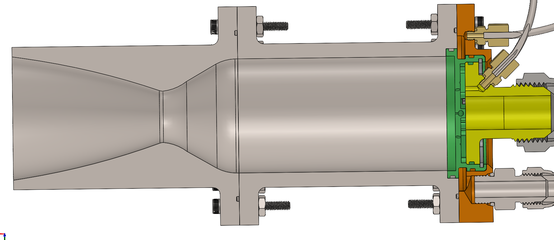
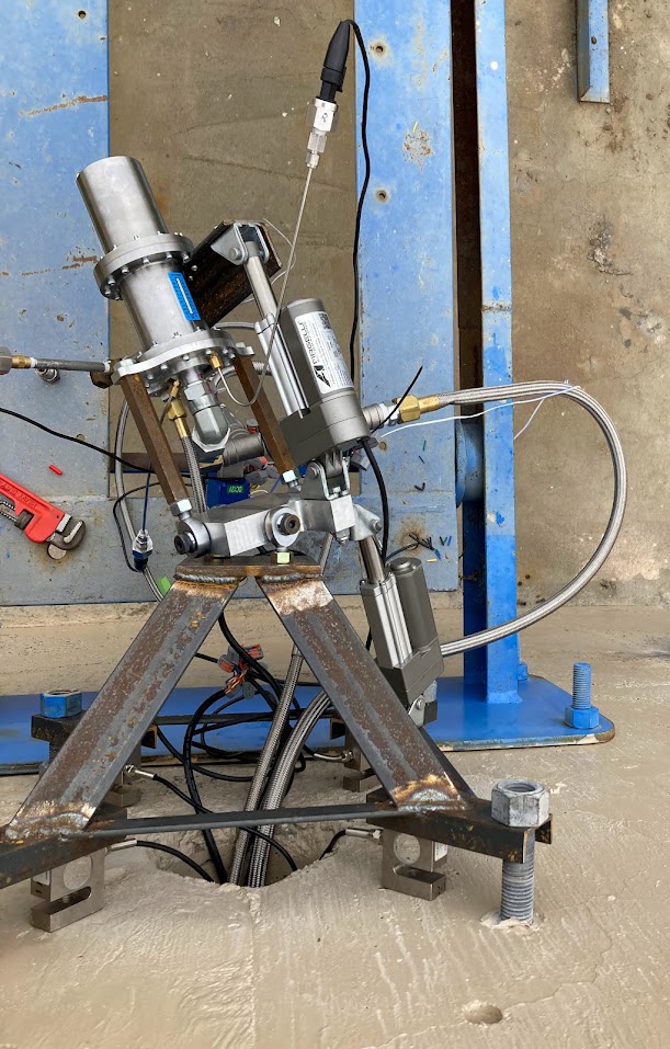
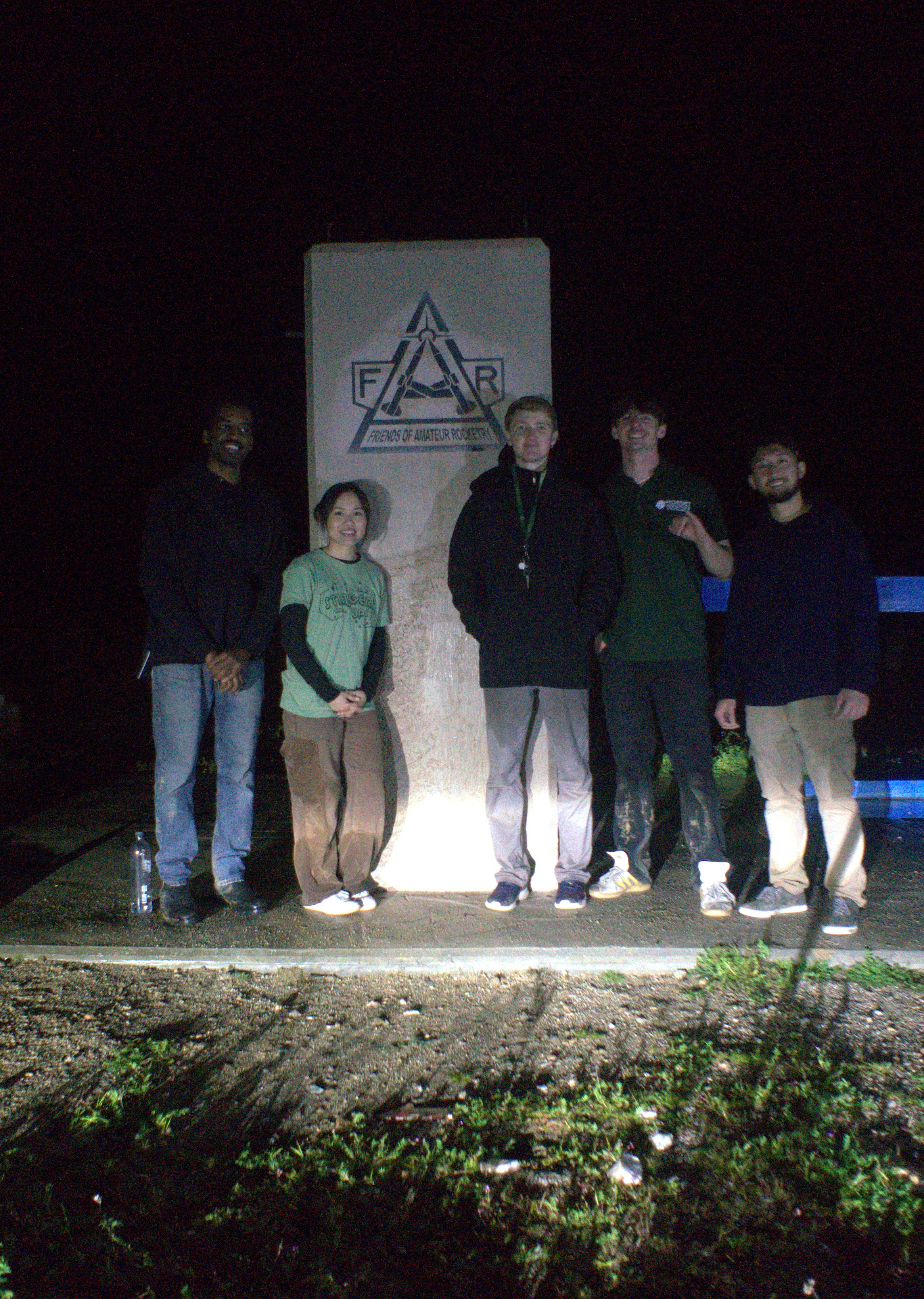
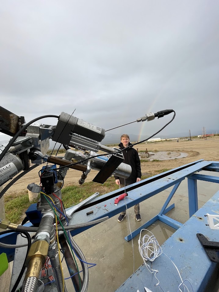
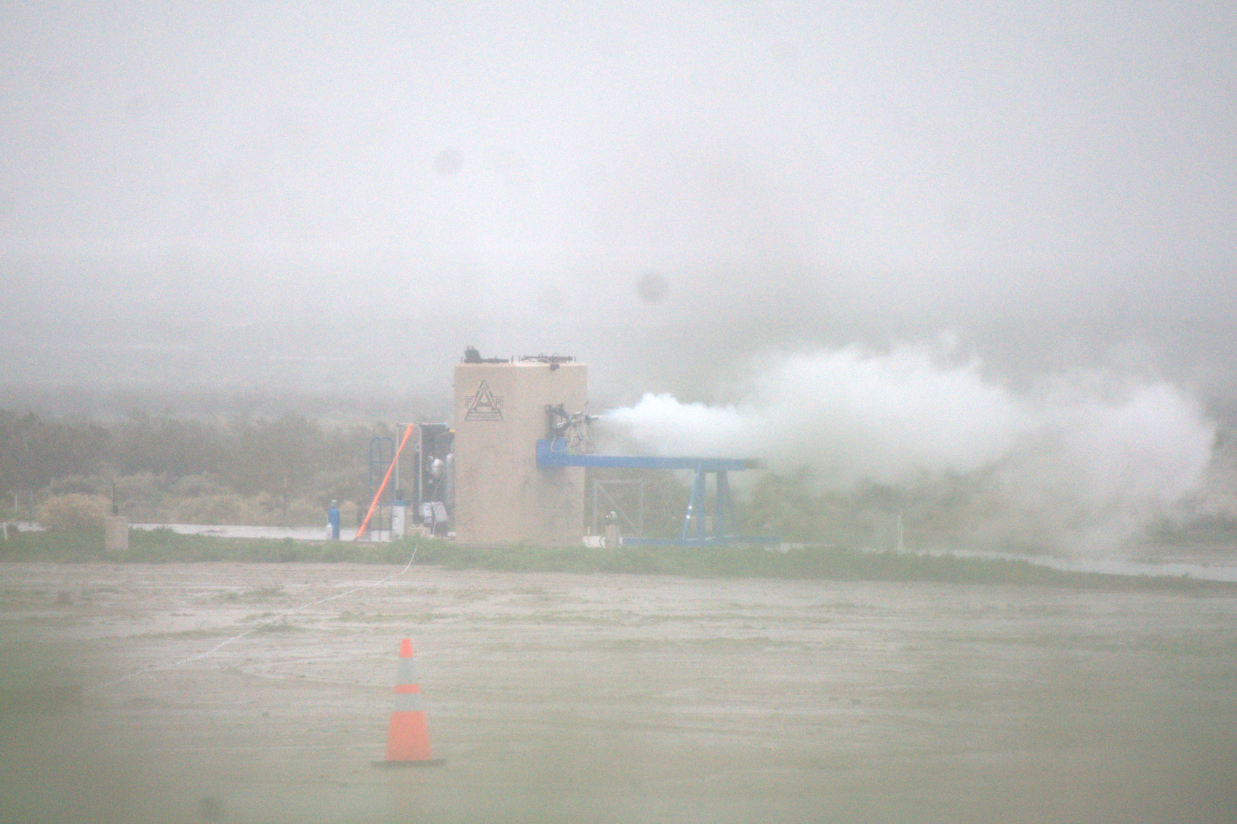
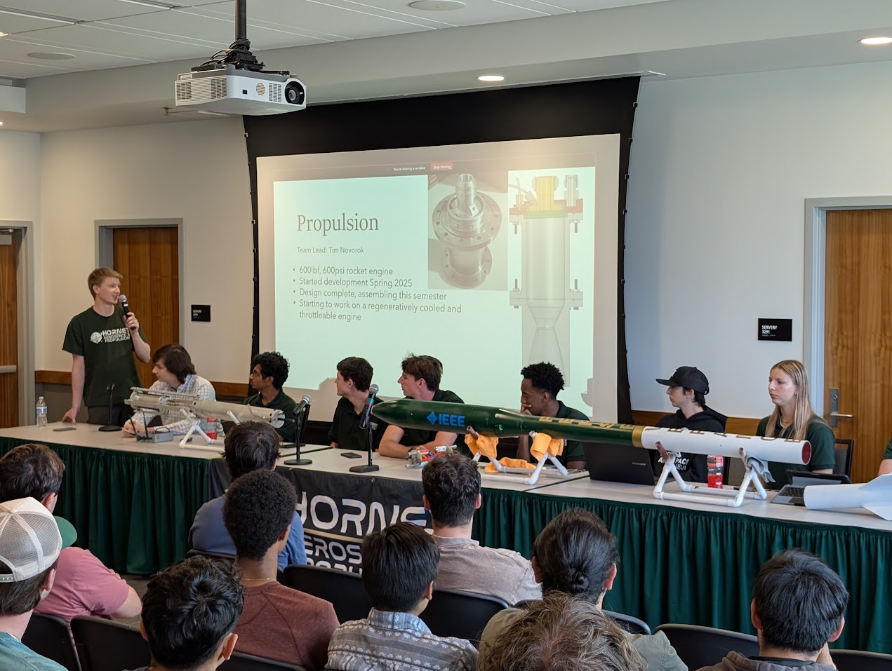
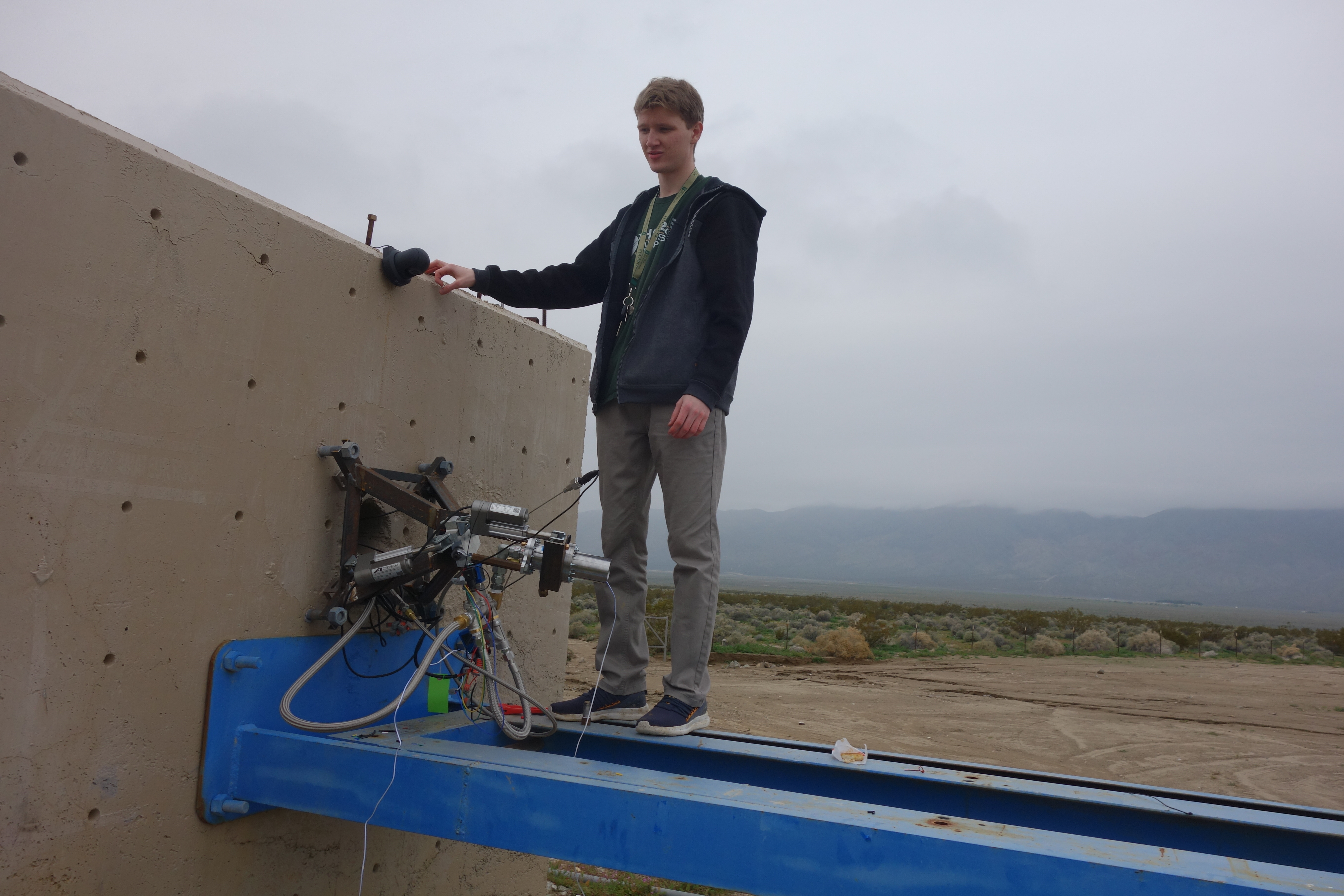
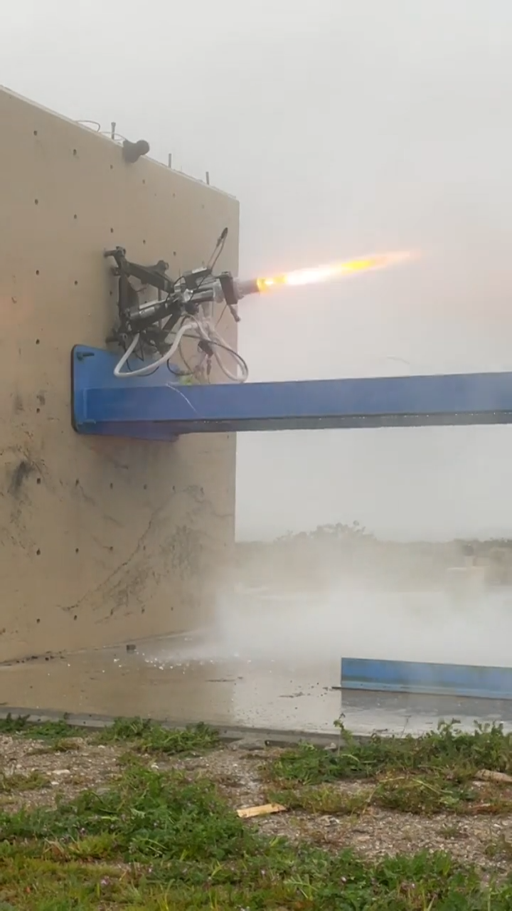
This is my second rocket engine developed as Liquid Propulsion Lead at HAP (Hornet Aerospace & Propulsion). It is designed to produce 600 lbf, at 600 psi. This project was started in the Spring 2025 semester, and was hot fired for the first time on Jan 3, 2026. Issues with electronics and feed system caused the engine to be unable to sustain combustion. Specific issues experienced were GN2 leaks during tank pressurization and unreliable valve control due to water getting in electronics. An extreme ice buildup was observed on the engine during oxidizer load, which is believed to have melted and flooded the igniter during the ignition sequence. These issues will be solved and more testing will follow.
General Design
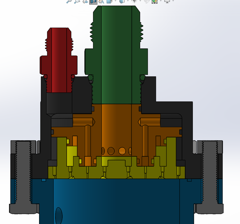
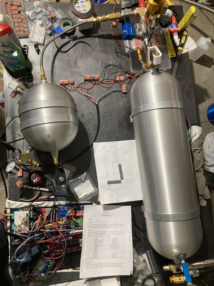
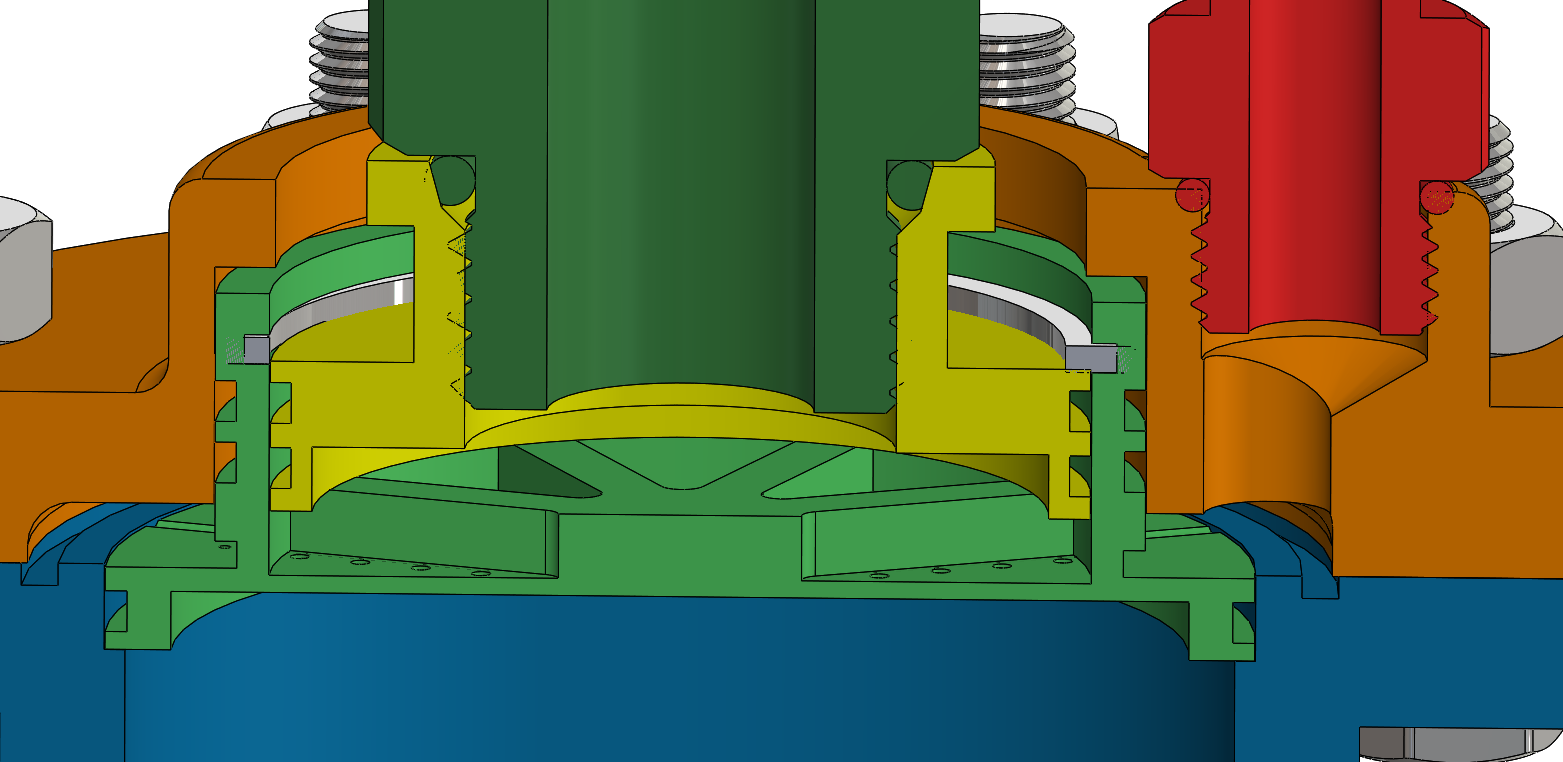
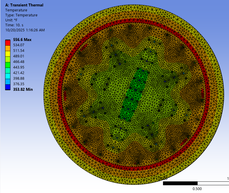
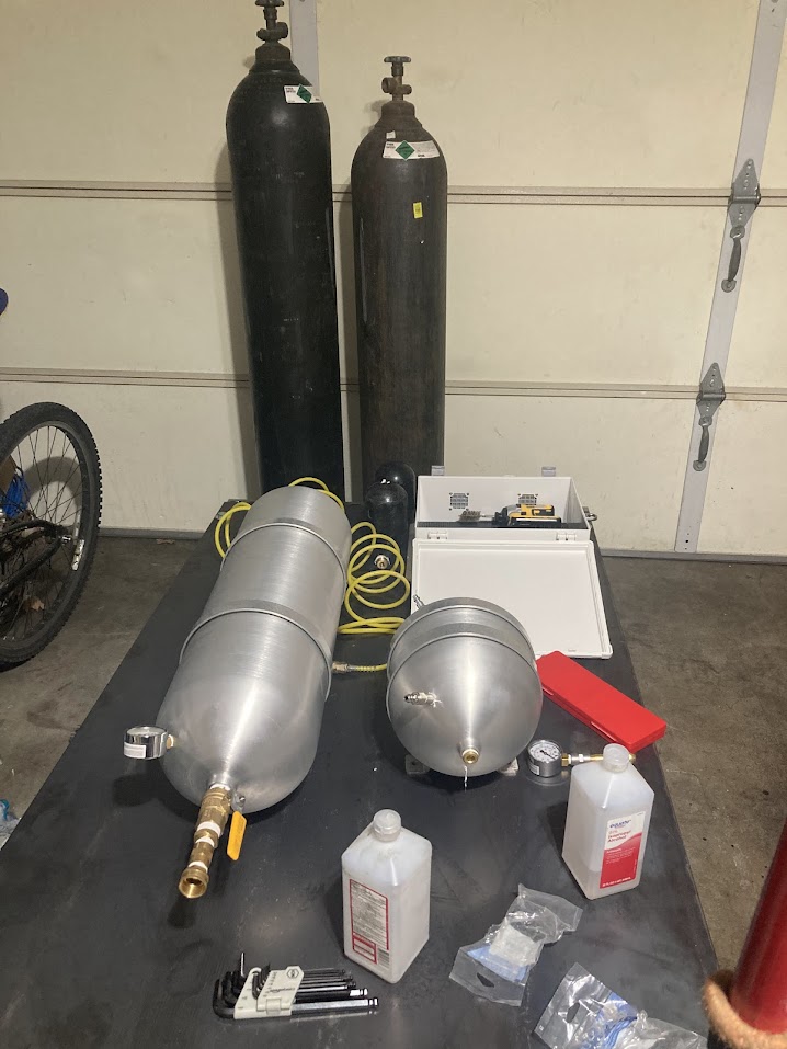
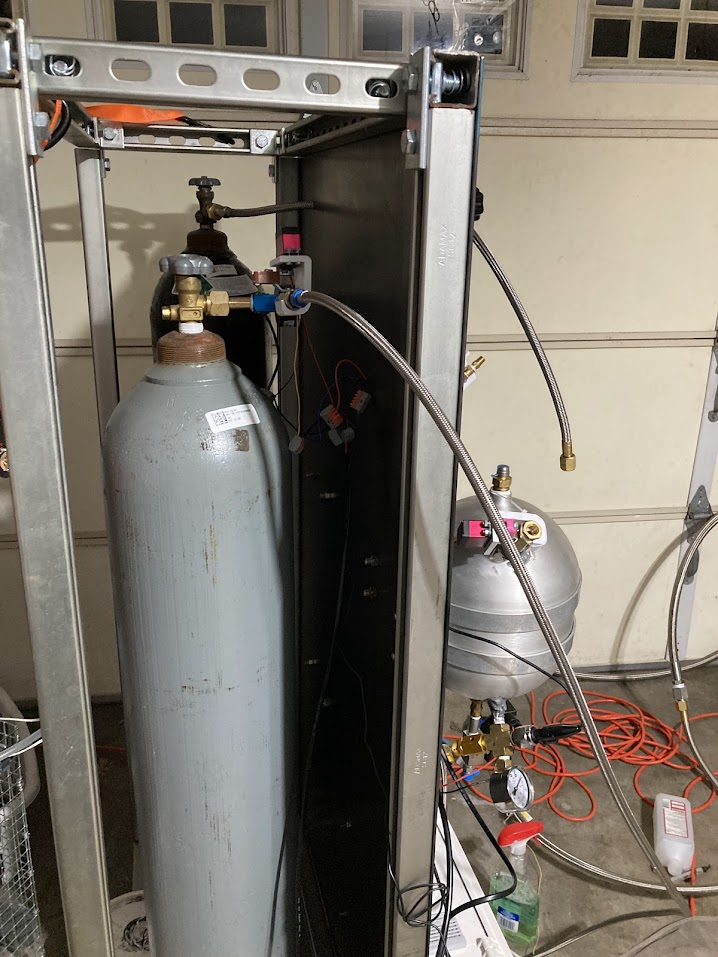
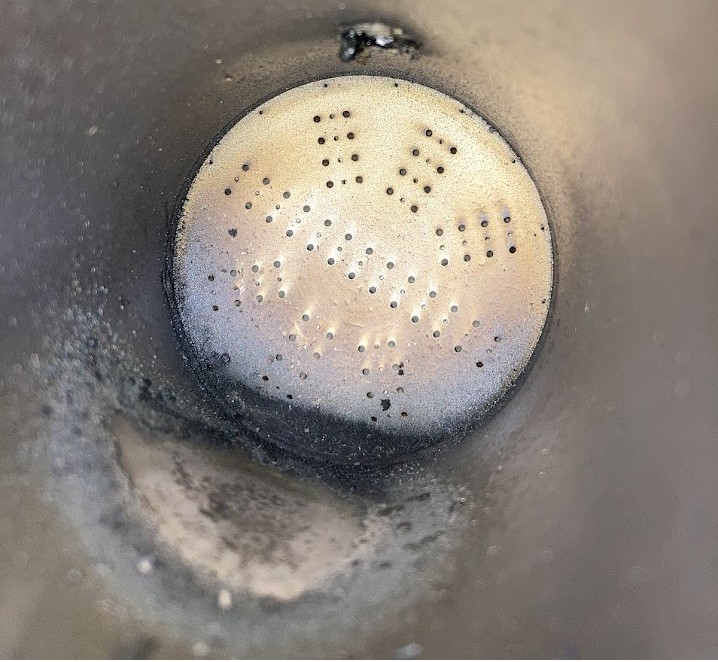
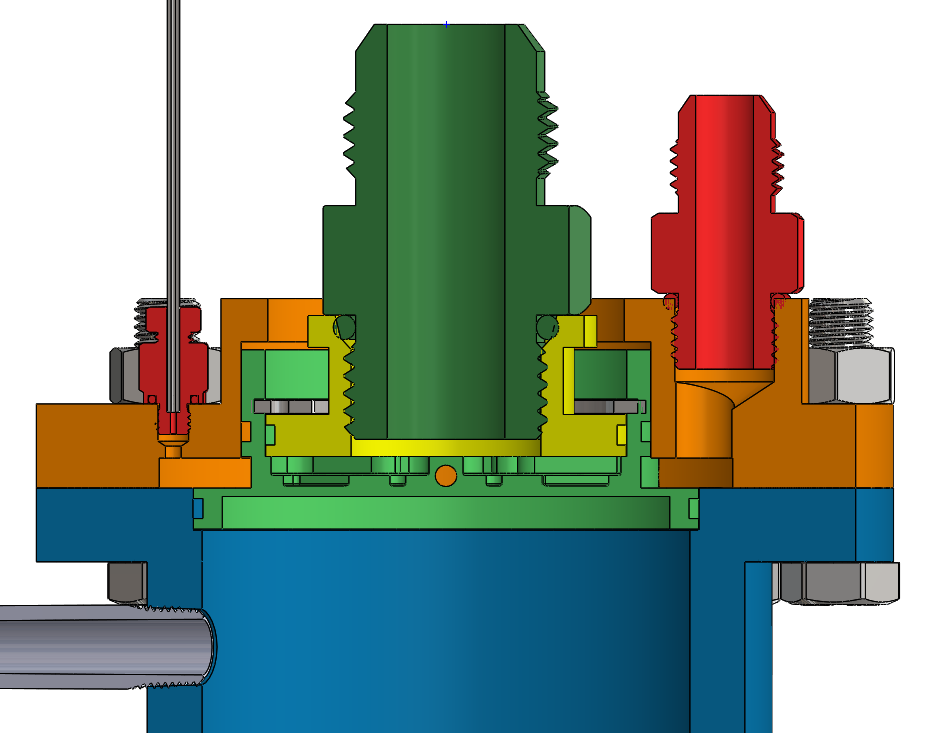
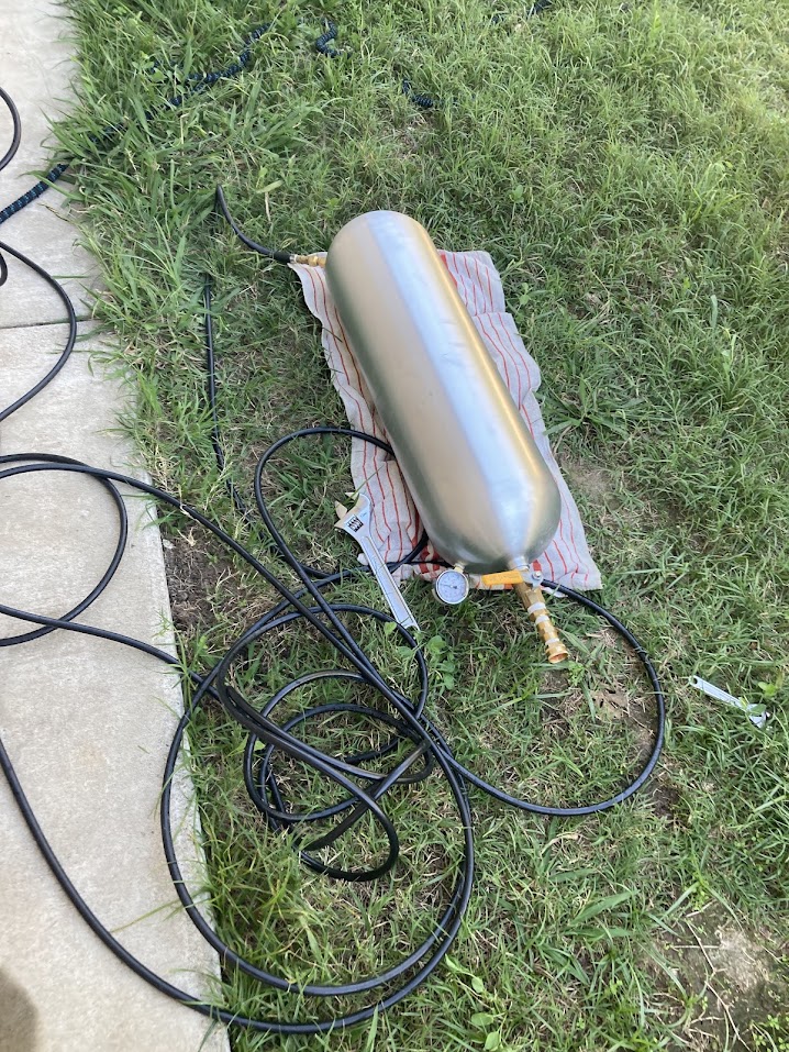
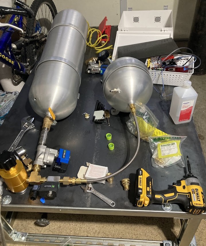
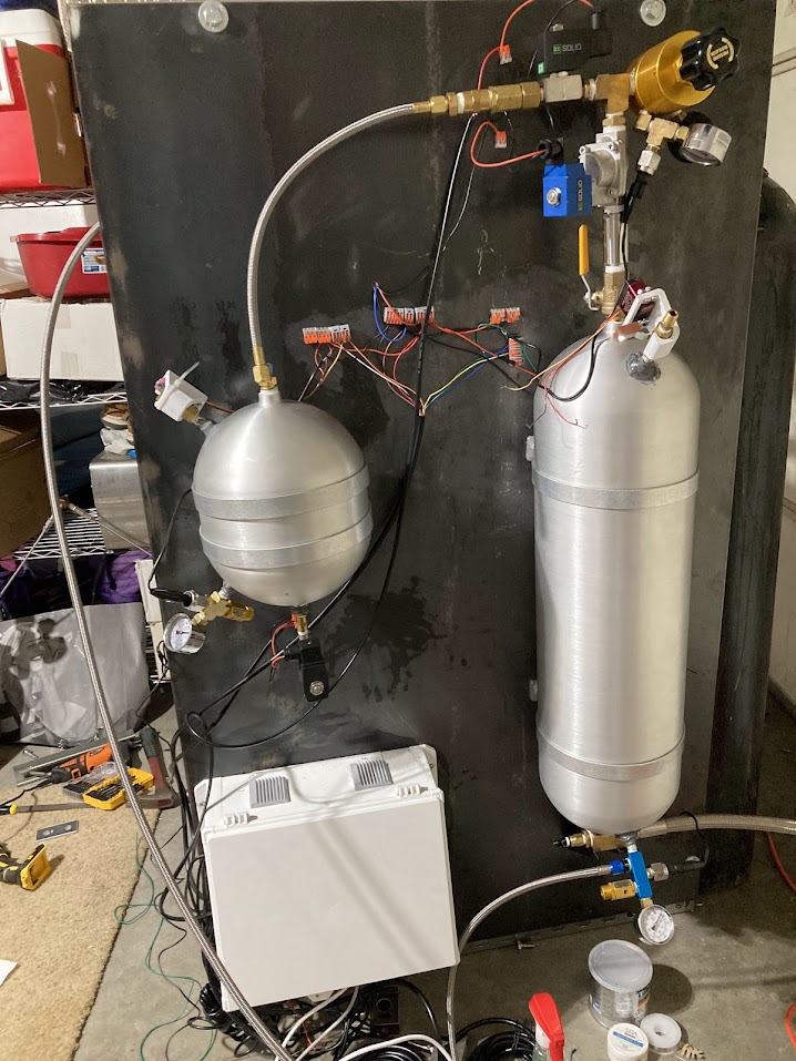
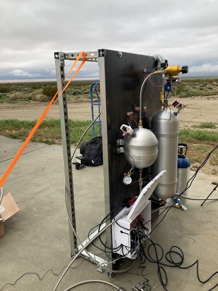
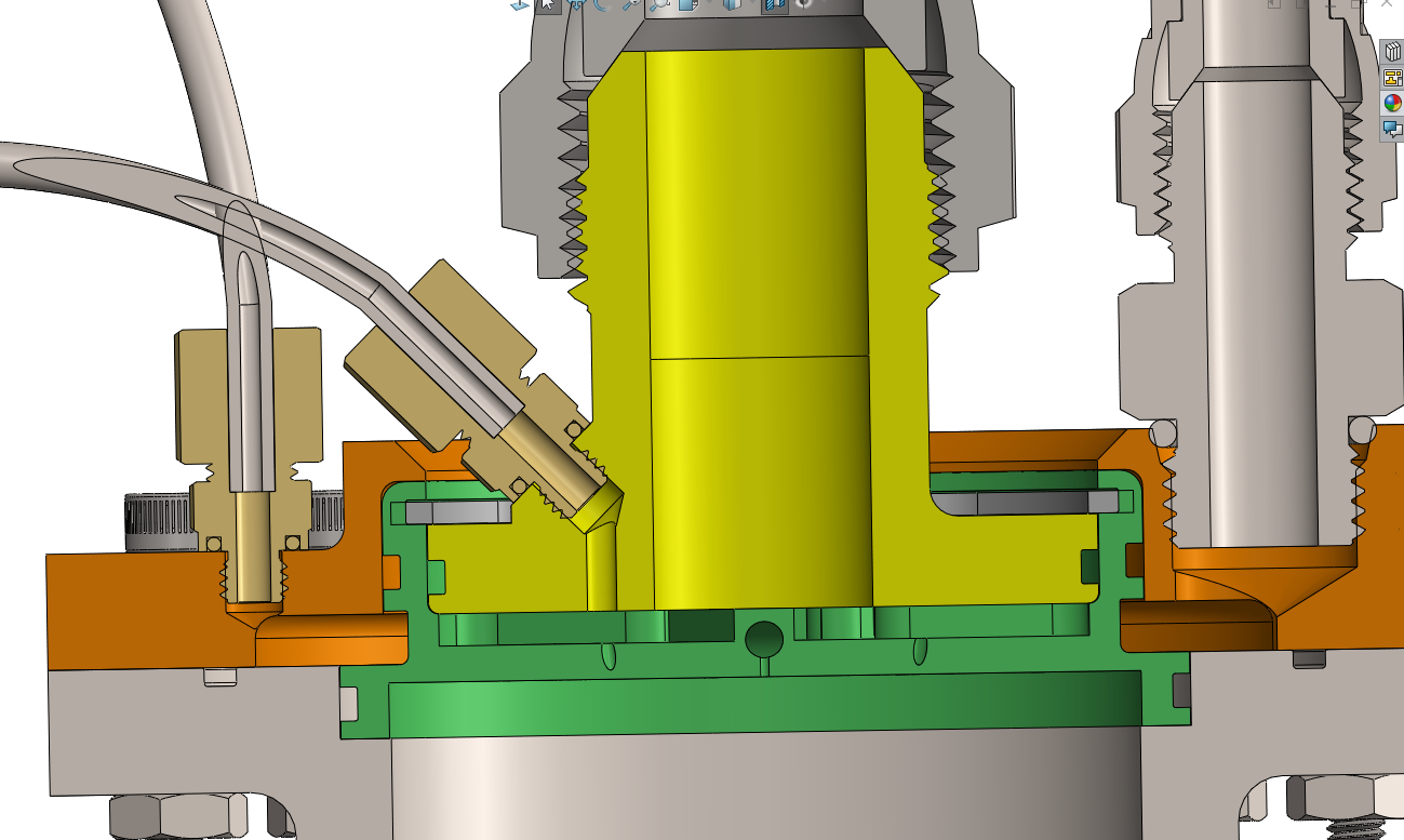
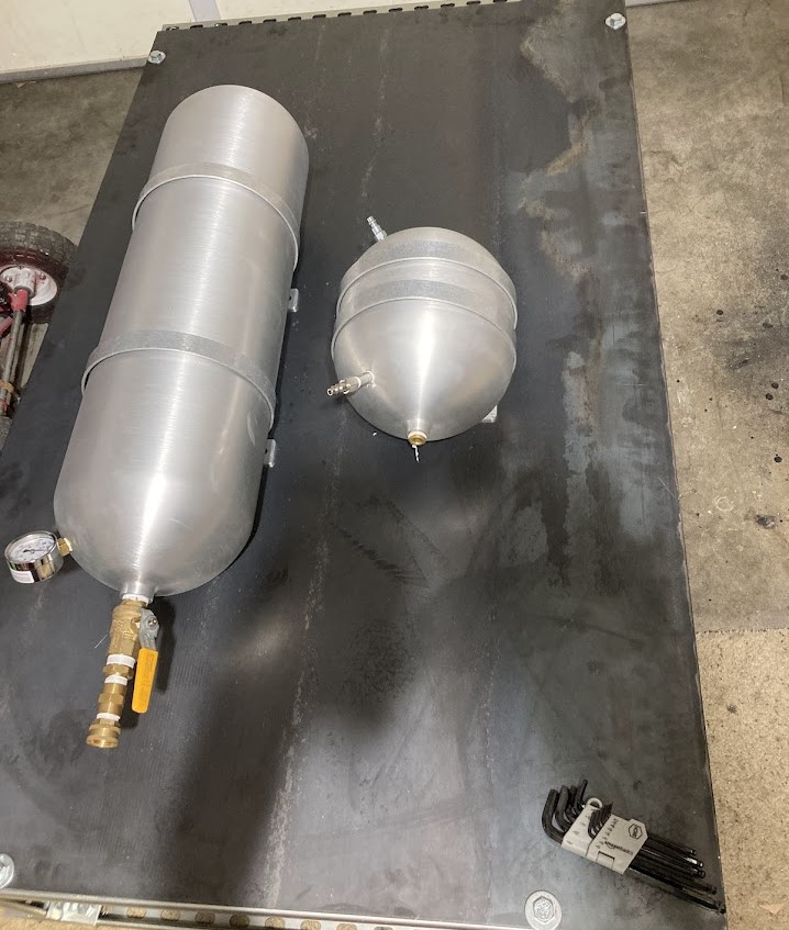
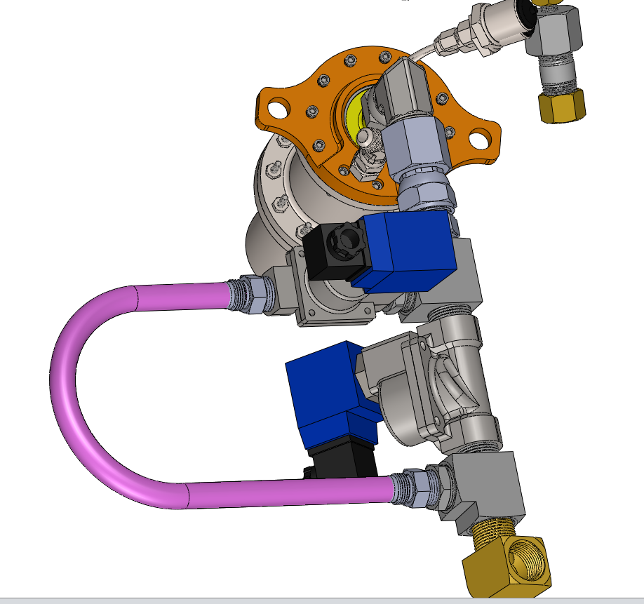
The engine utilizes IPA/N₂O as propellants at a MR of 3.5. The injector is a triplet impinging design, O-F-O. Film cooling is used as the primary cooling method. The injector architecture is designed to be compatible with a future regeneratively cooled engine. The feed system uses 2 seamless aluminum tanks for the propellants, and nitrogen is used to pressurize the tanks.
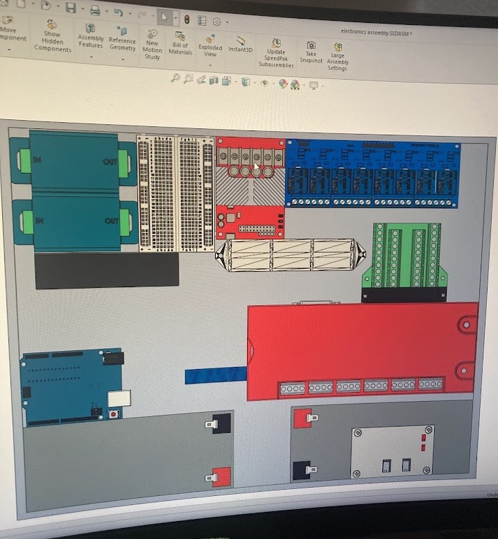
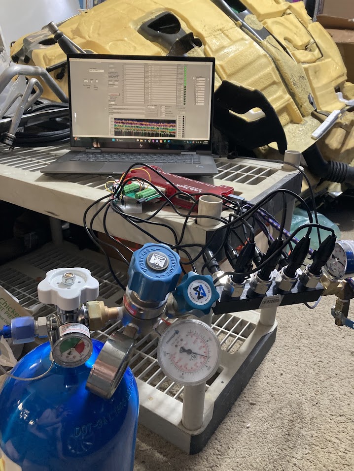
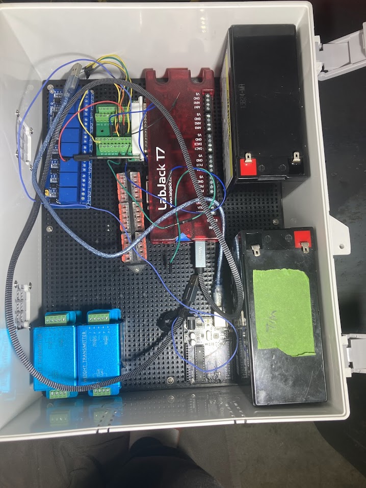
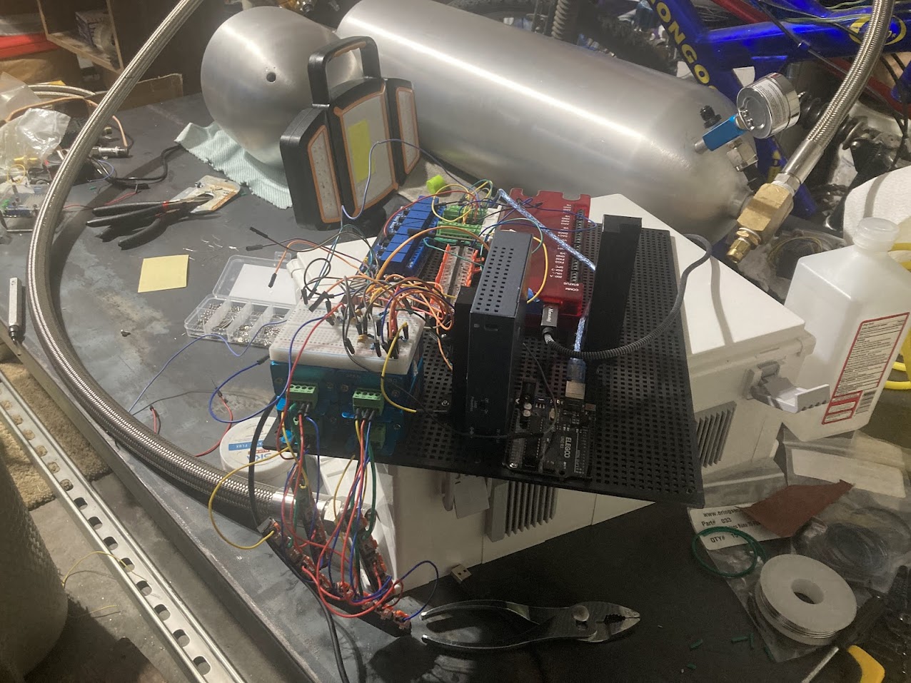
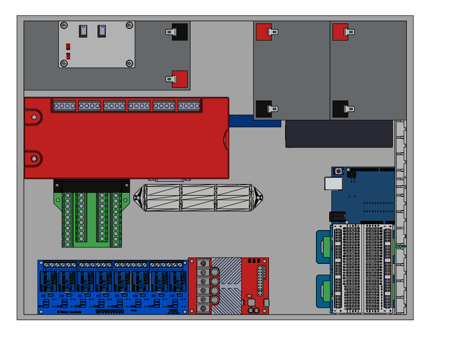
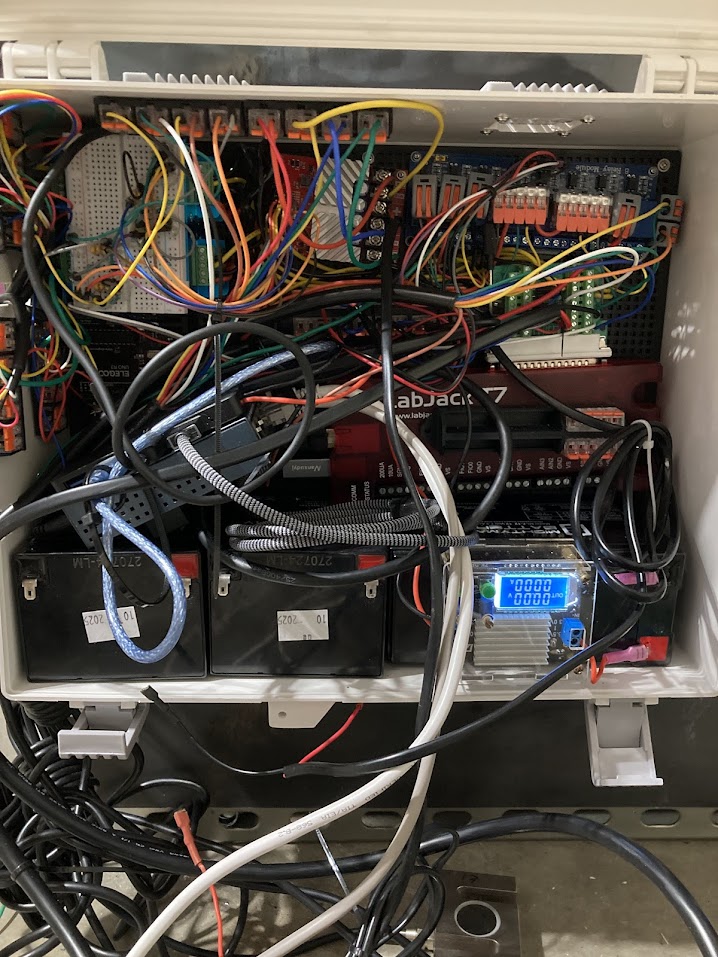
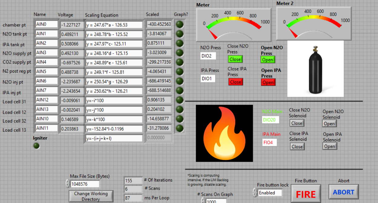
The control system for the engine and feed system is a modified version of LabJack's LJStreamM. It runs on a LabJack T7 on the feed system and allows a user to see live data/send commands to the control system through a LabVIEW GUI. A portion of the GUI is shown below.
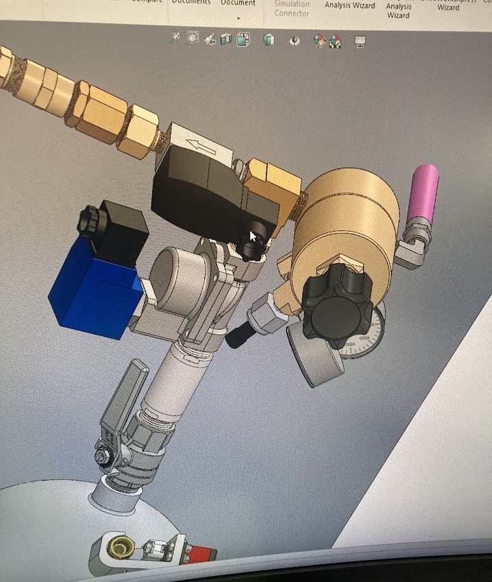
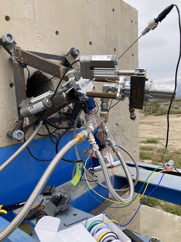
An old version of the CAD is shown below. It shows the engine mounted to the large horizontal test stand at FAR through a static mount without TVC hardware. An early version of the feed system is also displayed in the CAD.
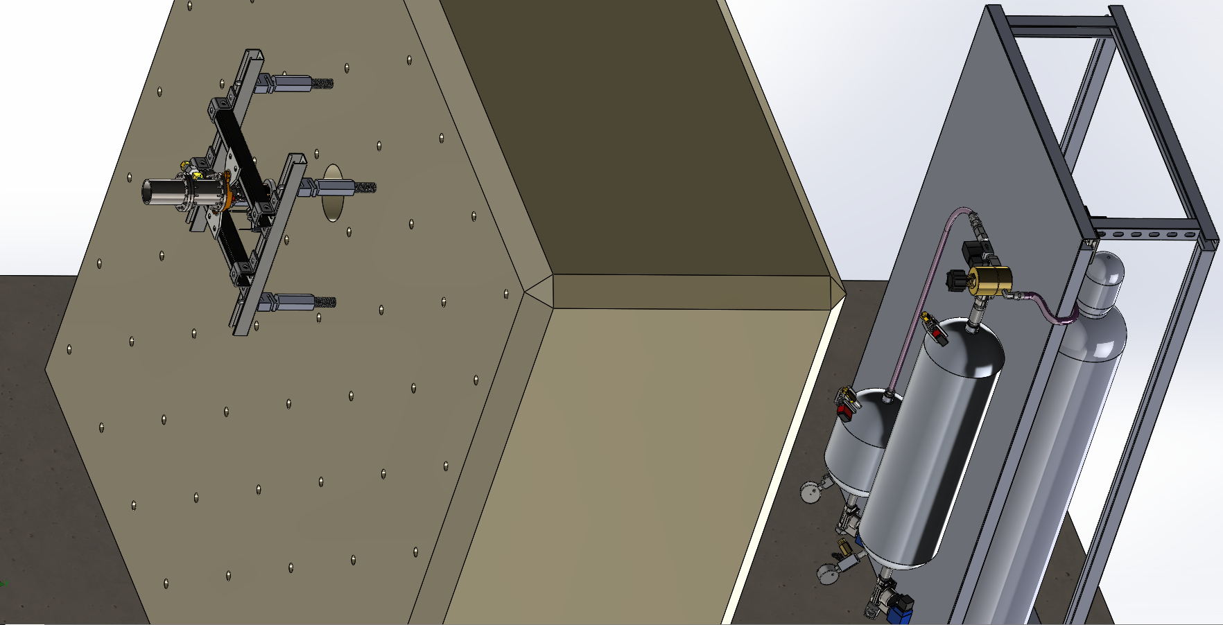
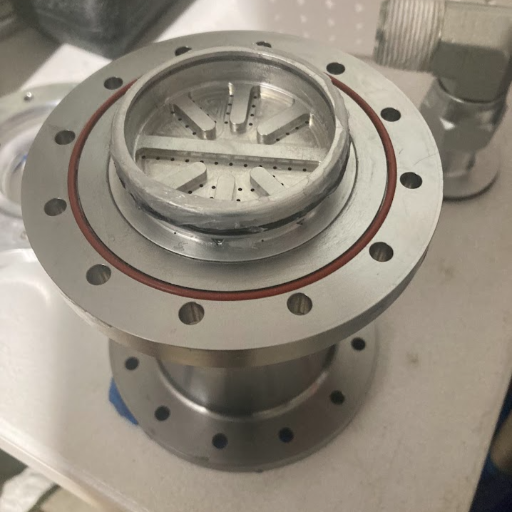
Photo Gallery